> ## Documentation Index
> Fetch the complete documentation index at: https://docs.taxibutler.com/llms.txt
> Use this file to discover all available pages before exploring further.
# Assembling the Floorstand KIOSK
> Learn how to assemble & install the Floorstand version of the Taxi Butler KIOSK.
* 1x 21.5" Screen
* 1x NFC Module
* 2x Screws
* 1x Quickstart flyer
* 1x Base Plate
* 1x Floor Stand
* 1x Screen Stand
* 1x Screen Stand Back Plate
* 1x Screen Mounting Plate
* 1x Power Cable
* 2x Printer Housing Keys
* 1x Pry Tool
* 12x Black M4 Screws
* 4x Silver M4 Screws
* 1x Silver M4 Screw with Washer
* 4x Expansion Bolts, Nuts and Washers
## Assembling the floor stand
The stand is made up of three parts:
1. The Base Plate
2. The Floor Stand (houses the power connection)
3. The Screen Stand (houses the printer and where the screen attaches).
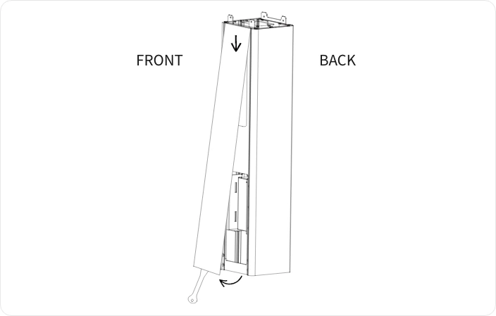 1. **Use the Pry Tool provided to gently pry open the acrylic panel** on the front of the Floor Stand. Insert the tool into the gap at the bottom of the panel and lift away the bottom part of the panel.
2. **Pull down on the top part of the panel to remove it**. This exposes 4 screw holes at the front of the Floor Stand.
1. **Use the Pry Tool provided to gently pry open the acrylic panel** on the front of the Floor Stand. Insert the tool into the gap at the bottom of the panel and lift away the bottom part of the panel.
2. **Pull down on the top part of the panel to remove it**. This exposes 4 screw holes at the front of the Floor Stand.
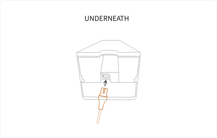 **Plug in the Power Cable** into the power supply unit inside of the Floor Stand at the bottom.
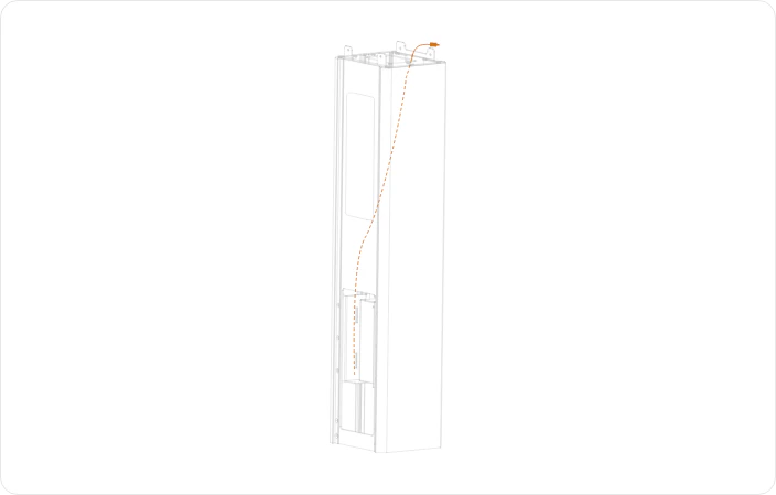 **Run the power cable from the power supply unit up** through the stand and use the opening slit at the back to pass the cable through the centre of the slit.
Leave the cable hanging out for now.
**Run the power cable from the power supply unit up** through the stand and use the opening slit at the back to pass the cable through the centre of the slit.
Leave the cable hanging out for now.
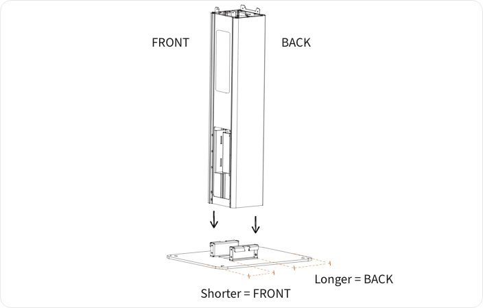 Place the Floor Stand onto the Base Plate.
The Base Plate is rectangular with the vertical fixings positioned more to one side. The back of the Floor Stand (the side with the U-shaped cutout for cable routing) should be on the side where there is the most space.
Place the Floor Stand onto the Base Plate.
The Base Plate is rectangular with the vertical fixings positioned more to one side. The back of the Floor Stand (the side with the U-shaped cutout for cable routing) should be on the side where there is the most space.
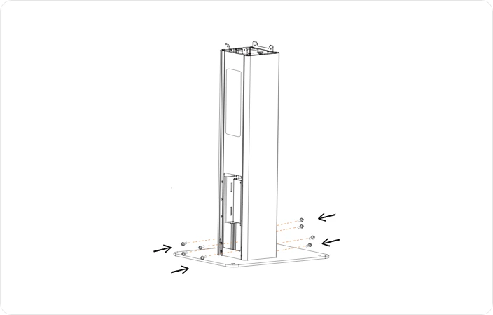 **Use 8x black M4 screws to secure the Floor Stand** to the Base Plate.
Use 4 screws at the front and 4 at the back.
Optional: You can secure the Base Plate to the ground using the 4x M8 Expansion Bolts, nuts and washers, and the pre-drilled holes.
**Use 8x black M4 screws to secure the Floor Stand** to the Base Plate.
Use 4 screws at the front and 4 at the back.
Optional: You can secure the Base Plate to the ground using the 4x M8 Expansion Bolts, nuts and washers, and the pre-drilled holes.
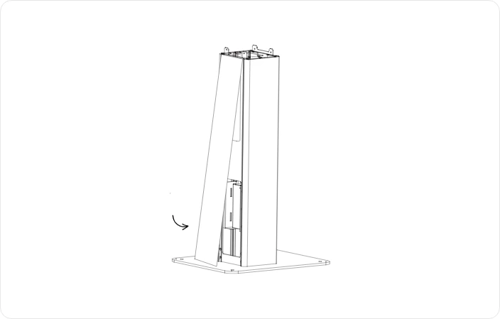 **Reattach the acrylic panel** on the front of the Floor Stand.
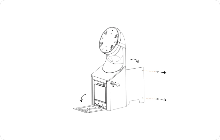 1. On the Screen Stand, **use one of the Printer Housing Keys to open the front panel** (where the printer is housed)
2. **Open the back panel by unscrewing the 2 screws** on the right side. Put these 2 screws to one-side, they will be used again later. This exposes 2 holes at the front and 2 at the back for mounting the Screen Stand to the Floor Stand.
1. On the Screen Stand, **use one of the Printer Housing Keys to open the front panel** (where the printer is housed)
2. **Open the back panel by unscrewing the 2 screws** on the right side. Put these 2 screws to one-side, they will be used again later. This exposes 2 holes at the front and 2 at the back for mounting the Screen Stand to the Floor Stand.
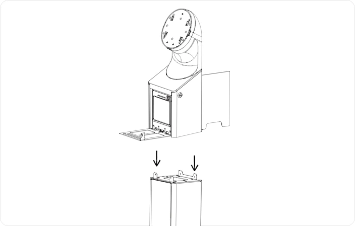 Align and **gently lower the Screen Stand** onto the Floor Stand.
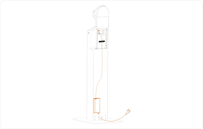 1. **Connect the power cable** that you left hanging out, up into the connector on the left hand side of the Screen Stand.
2. Use the velcro strap to secure the cable into place.
3. Remove any excess cable by pulling it gently into the empty space in the Floor Stand.
1. **Connect the power cable** that you left hanging out, up into the connector on the left hand side of the Screen Stand.
2. Use the velcro strap to secure the cable into place.
3. Remove any excess cable by pulling it gently into the empty space in the Floor Stand.
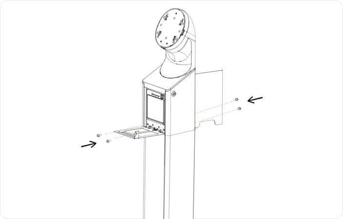 1. **Use 4x Black M4 screws to secure the Screen Stand** to the Floor Stand. 2 at the front and 2 at the back.
2. You can now close the front panel.
3. Leave the back panel open for now.
## Assembling the screen to the stand
1. **Use 4x Black M4 screws to secure the Screen Stand** to the Floor Stand. 2 at the front and 2 at the back.
2. You can now close the front panel.
3. Leave the back panel open for now.
## Assembling the screen to the stand
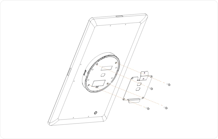 **Secure the Screen Mounting Plate to the back of the Screen** using 4x Silver M4 screws.
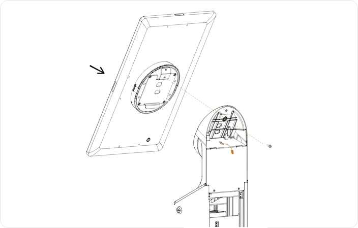 **Lift the Screen to the Screen Stand and secure it** using 1x Silver M4 Screw with Washer.
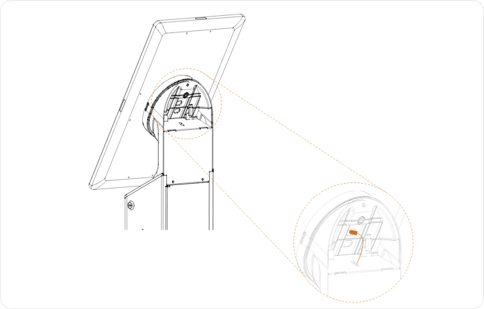 **Plug in the USB-C power cable** from the Screen Stand into the connector in the back of the Screen using the provided hole.
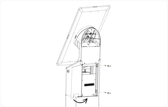 **Close the back panel** and secure with the 2 screws you removed earlier in step 7 of the stand assembly.
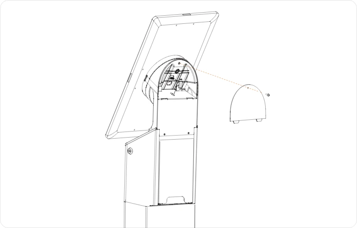 1. **Fit the Screen Stand Back Plate** by slotting the two notches at the bottom into their respective slits.
2. **Secure it in place at the top of the panel** using the M3 screw that is already screwed in the Screen Stand Back Plate.
1. **Fit the Screen Stand Back Plate** by slotting the two notches at the bottom into their respective slits.
2. **Secure it in place at the top of the panel** using the M3 screw that is already screwed in the Screen Stand Back Plate.
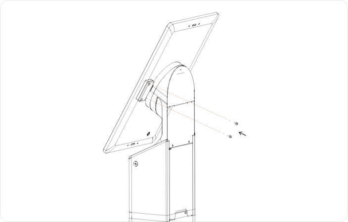 **Attach the NFC Module** to the right-hand side of the Screen (when facing the front). Secure using the 2 screws provided.
Tighten gently to avoid stripping the threads.
In some cases, the NFC Module may already be installed on the screen.
## Powering on the device
**Plug the Power Cable** from the bottom of the Floor Stand into a mains power outlet.
**Find and press the Power button** on the lower right back side of the Screen.
**Attach the NFC Module** to the right-hand side of the Screen (when facing the front). Secure using the 2 screws provided.
Tighten gently to avoid stripping the threads.
In some cases, the NFC Module may already be installed on the screen.
## Powering on the device
**Plug the Power Cable** from the bottom of the Floor Stand into a mains power outlet.
**Find and press the Power button** on the lower right back side of the Screen.